
 EN
EN
 ar
ar bg
bg hr
hr cs
cs da
da nl
nl fi
fi fr
fr de
de el
el hi
hi it
it ko
ko no
no pl
pl pt
pt ro
ro ru
ru es
es sv
sv tl
tl iw
iw id
id lv
lv lt
lt sr
sr sk
sk sl
sl uk
uk vi
vi et
et hu
hu th
th tr
tr fa
fa ms
ms hy
hy ka
ka ur
ur bn
bn mn
mn ta
ta kk
kk uz
uz ku
ku
piezometer well
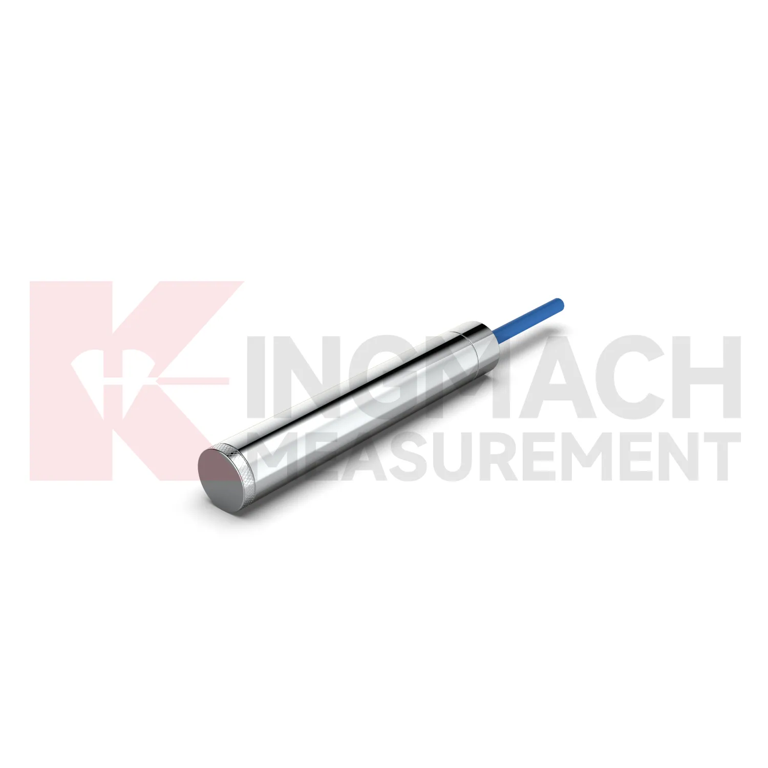
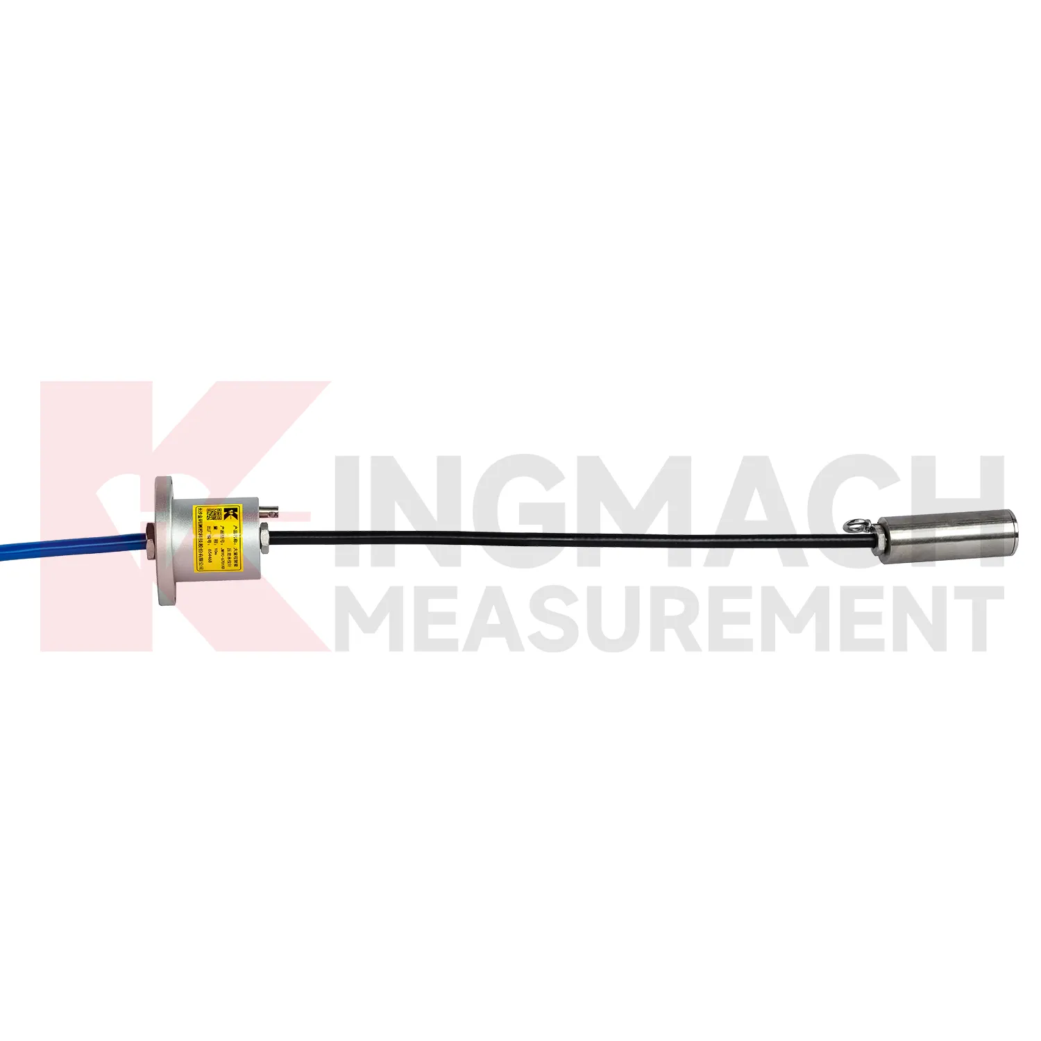
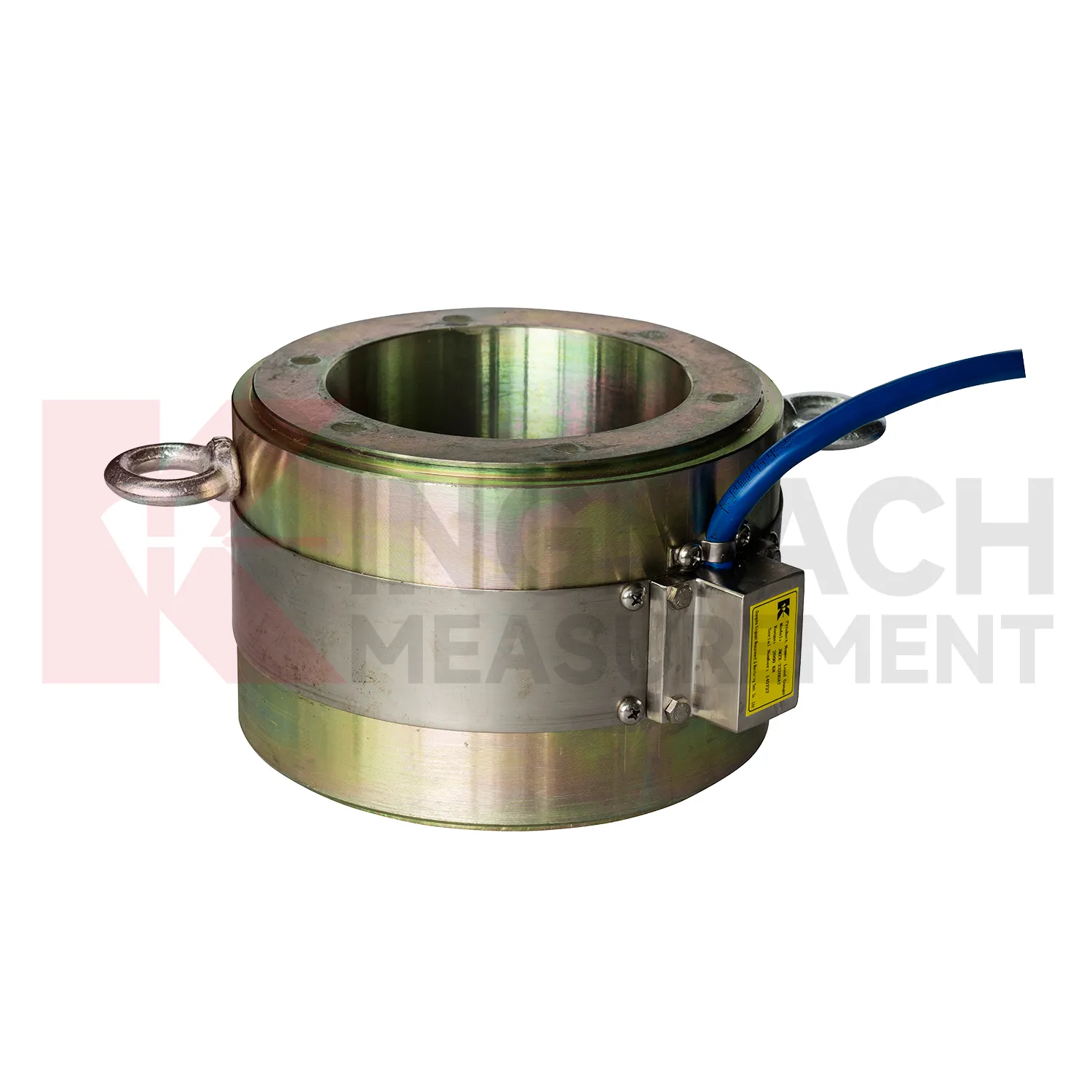
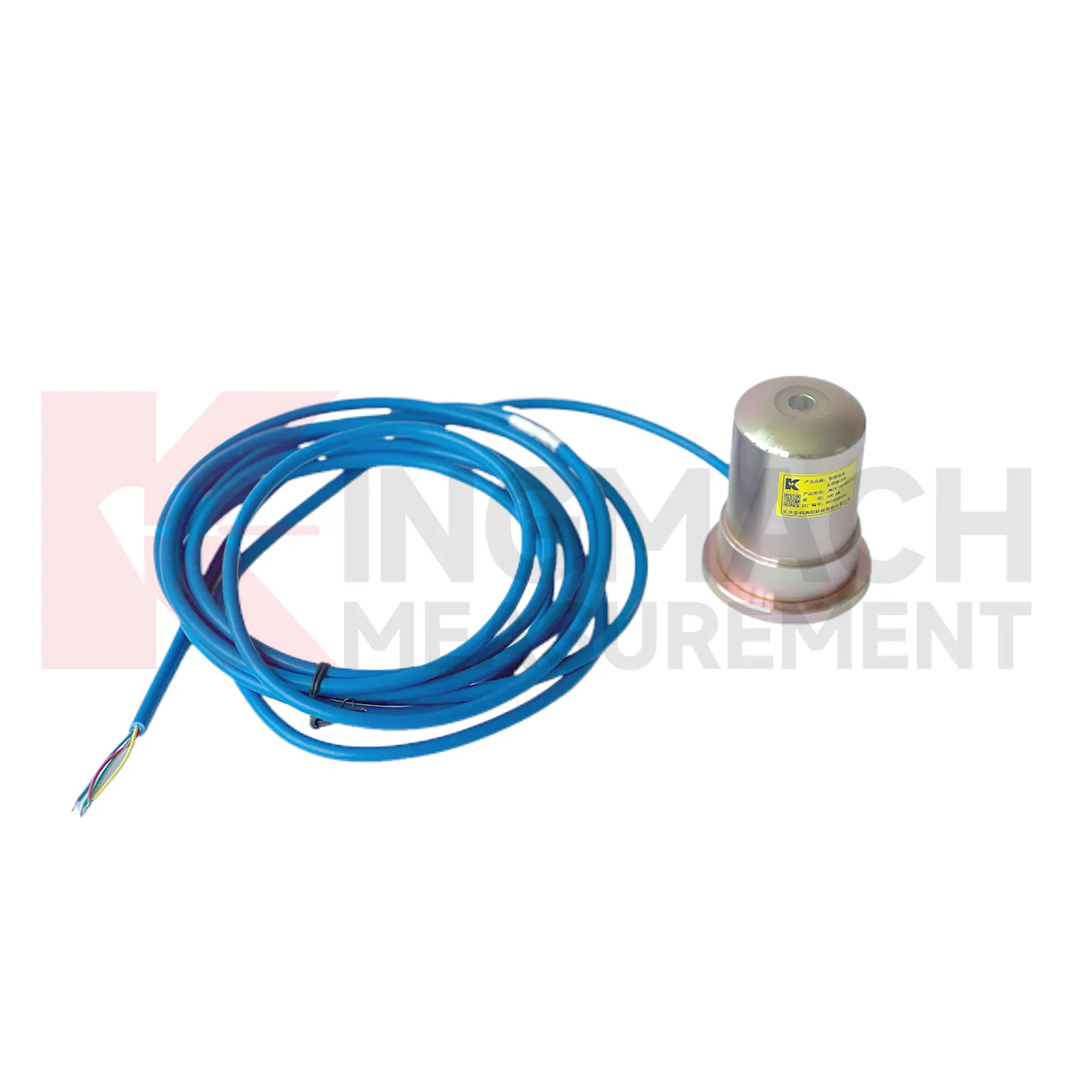
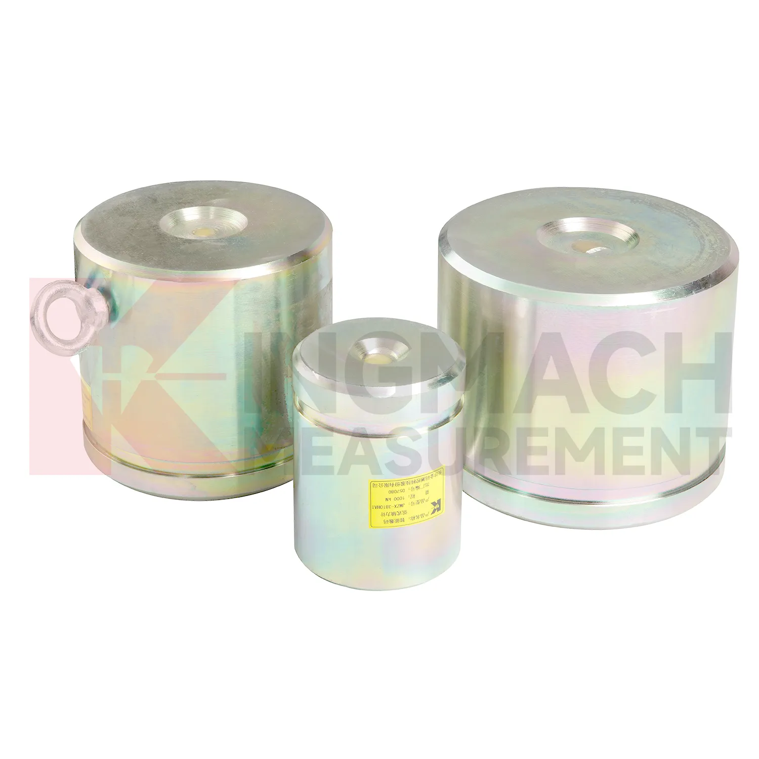
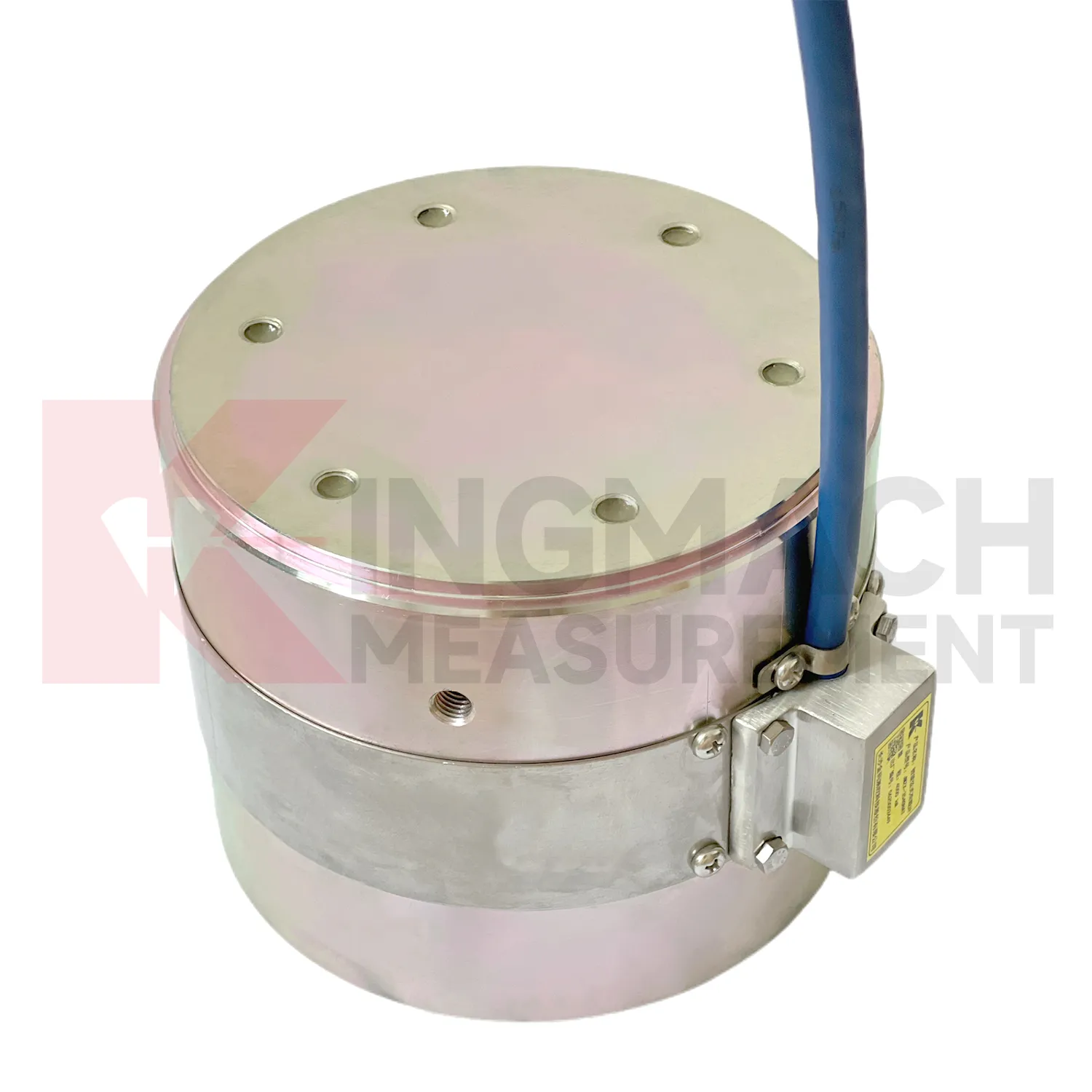
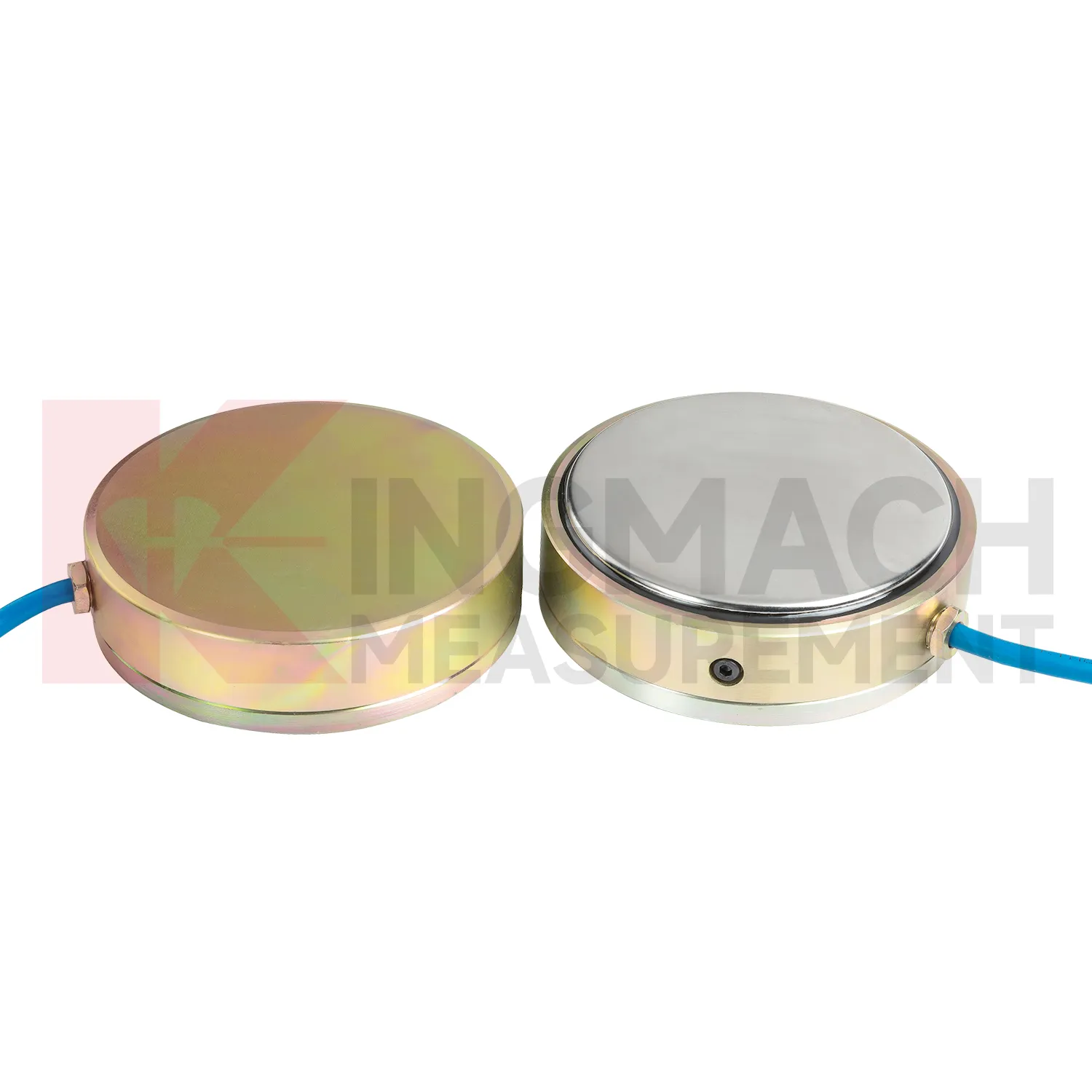
Kingmach piezometer well is developed for civil infrastructure where readings must remain usable after dust, vibration, water, and long cable runs enter the job. Product files describe vibrating wire based designs, smart chips, digital detection, strong anti-interference transmission, waterproof insulation, and automatic temperature correction. On the solid load cell JMZX-35XXHAT, the listed range runs from 1000 kN to 10000 kN with 0.1 kN resolution and 0.5%FS precision. On the hollow JMZX-3XXXHAT series, the listed range covers 500 kN to 8000 kN and the record memory can store 800 measurement entries. On the JMZX-38XXHAT axial force meter, the instrument can display axial force directly in kN. These details suit projects where force monitoring is part of acceptance, construction control, or long term service review. Kingmach's product grouping also supports mixed monitoring networks, where load readings sit beside water level, piezometer, displacement, settlement, and tilt data. For purchasing teams, this means the specification should include not only the sensor body, but also compatible readout equipment, cable length, protection accessories, calibration needs, and the reporting method expected by the owner. That reduces changes after the site work has already started. In practice, this means the specification should name the monitored member, expected reading frequency, installation exposure, and the person responsible for accepting the first stable value.
Application of piezometer well
In monitoring networks that cover several structures, piezometer well gives force and pressure points a place beside displacement, settlement, tilt, vibration, water level, and environmental data. The project pain point is interpretation across many channels. A force increase in a foundation pit may be normal after excavation, while a similar increase on a dam anchor after water level change may need closer review. Kingmach smart sensors can store model data, calibration coefficients, zero values, temperature data, and up to 800 records on relevant models. Load ranges across the family include 200 kN to 10000 kN for force products and 0.3 MPa to 8 MPa for earth pressure cells. When connected through readouts, data loggers, DTUs, or software platforms, these points can be reviewed by location and time. Good channel naming, consistent units, alarm thresholds based on design stages, and periodic field checks prevent the network from becoming a pile of disconnected numbers. Large networks also need a naming convention that crews can understand on site. A channel label that matches drawings, physical tags, and software screens prevents mistakes when alarms arrive during night work or bad weather. The platform should keep the raw reading history available, so later reviewers can see whether an alarm came from a real trend or a setup change.
The future of piezometer well
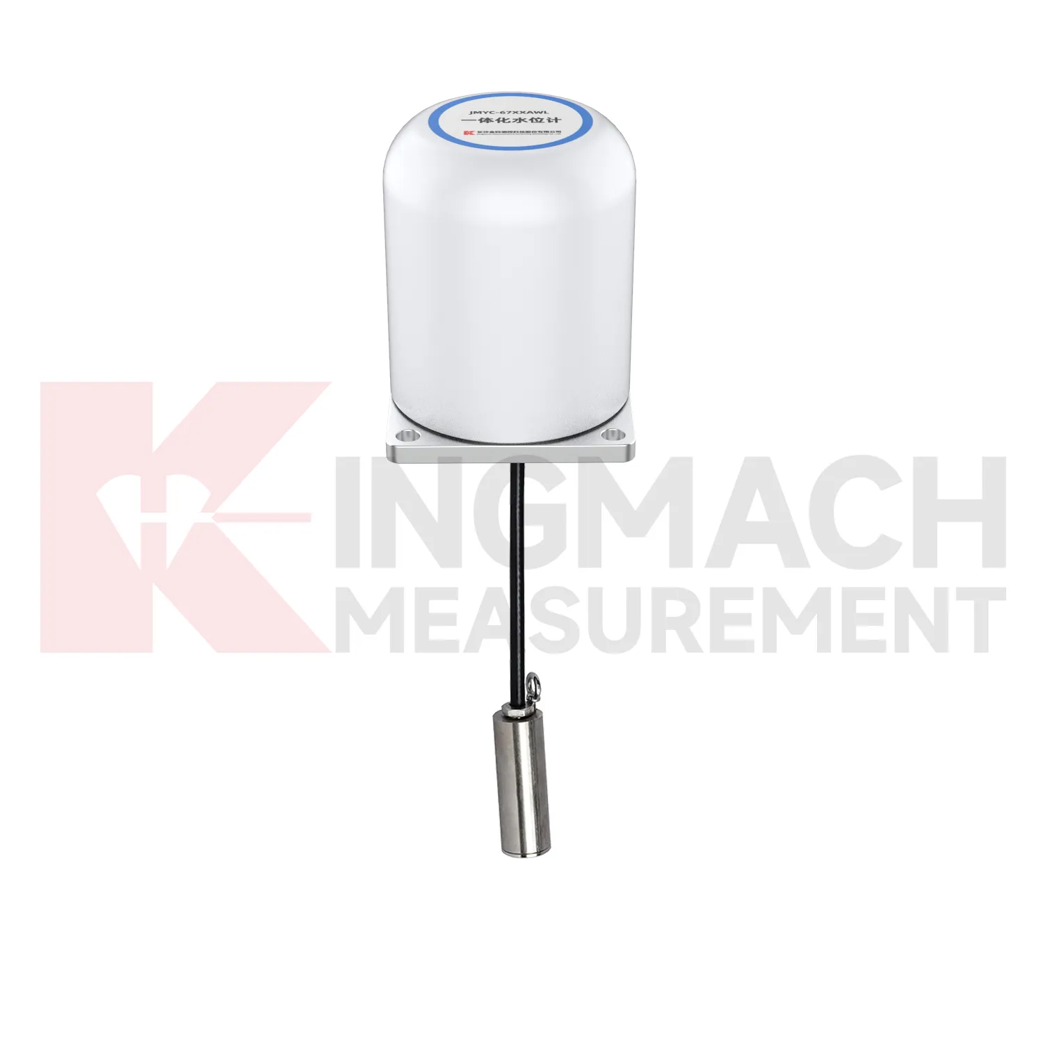
Industrial and test bench use of piezometer well will likely move toward automated verification. High capacity solid load cells with 0.5%FS precision and ranges up to 10000 kN can already support heavy compression tests, jack calibration work, and equipment checks. Future systems can connect these instruments to local software that records test stages, operator notes, temperature, overload events, and calibration status. That reduces the risk of a handwritten record being separated from the force data. Edge acquisition can also prevent common errors by warning when the zero point is unstable, the load rate is outside procedure, or the sensor range is being approached too quickly. Kingmach's smart memory features fit this direction because the sensor can carry identity and calibration background. The strongest future workflow will combine rugged hardware, automatic records, and simple review tools, so a test can be repeated months later with the same measurement basis. The same logic applies to factory tests and site acceptance.
Care & Maintenance of piezometer well
For piezometer well, installation quality usually determines whether later maintenance is simple or painful. Before loading, confirm the model, range, calibration coefficient, zero value, bearing surface, and cable route. Hollow load cells may cover 500 kN to 8000 kN, while solid load cells may reach 10000 kN, so capacity should be checked against both working load and possible overload. During installation, keep bearing plates flat and strong enough to avoid stress concentration, especially on axial force meters and compression load points. Protect cables from bending, pulling, welding sparks, crushing, and water entry at connectors. After the first stable reading, record temperature, channel name, instrument serial information, and site condition. During long term use, inspect sealing, cable jackets, junction boxes, and acquisition channels after rainfall, excavation changes, jacking, or impact. If a value drifts, check temperature, connector condition, zero history, and nearby sensors before assuming the instrument has failed. Document who made the check.
Kingmach piezometer well
piezometer well gives engineering teams a way to follow load behavior without dismantling the structure. In bridge bearing checks, anchor testing, steel support monitoring, pile tests, and retaining wall pressure work, the measured force can change before cracks, settlement, or visible deformation become obvious. Kingmach product information points to vibrating wire and smart sensing designs, built-in memory, automatic temperature correction, waterproof construction, and direct force display on selected models. These features matter because site readings are often taken by different people across long periods. The instrument needs to preserve its identity and calibration background even when the reading method changes from manual inspection to automated collection. The most useful force record is modest but complete: point name, model, range, coefficient, temperature, cable condition, acquisition channel, and the event that preceded the reading. That is enough to make later engineering review much less speculative. It also helps inspectors decide whether a changed value needs field checking or simple trend review.
FAQ
Q: How should piezometer well be selected for a bridge cable or anchor point? A: Start with expected force, lock-off load, possible overload, bearing geometry, and access for later inspection. Hollow load cells are commonly used where the anchor or cable passes through the center opening. Q: What range information is available from Kingmach hollow models? A: The JMZX-3XXXHAT series is listed from 500 kN to 8000 kN, with 0.1 kN sensitivity on the 500 kN model and 1 kN on larger listed models. Q: Why does temperature correction matter? A: Cable and anchor readings can move with temperature, so built-in temperature measurement helps reduce false interpretation. Q: Can readings be stored inside the sensor? A: Smart hollow models list storage for 800 measurement records, including time, temperature, zero values, and correction data. Q: What should be checked after installation? A: Check seating, cable protection, connector sealing, zero value, first stable force, and matching channel name.
Reviews
Daniel Brown
Excellent environmental monitoring sensors. The data is consistent, and the system integrates smoothly with our existing setup.
Ryan Lewis
Fast delivery and excellent product quality. The accelerometers and tiltmeters are highly reliable. Strongly recommend this company.
Latest Inquiries
To protect the privacy of our buyers, only public service email domains like Gmail, Yahoo, and MSN will be displayed. Additionally, only a limited portion of the inquiry content will be shown.
Isabella***@gmail.comGermany
Hello, we are evaluating weir flow meters for a water management project. Please share accuracy deta...
Emma***@gmail.comCanada
Dear Sir/Madam, we are interested in displacement transducers and settlement sensors for a geotechni...