 ar
ar bg
bg hr
hr cs
cs da
da nl
nl fi
fi fr
fr de
de el
el hi
hi it
it ko
ko no
no pl
pl pt
pt ro
ro ru
ru es
es sv
sv tl
tl iw
iw id
id lv
lv lt
lt sr
sr sk
sk sl
sl uk
uk vi
vi et
et hu
hu th
th tr
tr fa
fa ms
ms hy
hy ka
ka ur
ur bn
bn mn
mn ta
ta kk
kk uz
uz ku
ku
load cell wiring diagram
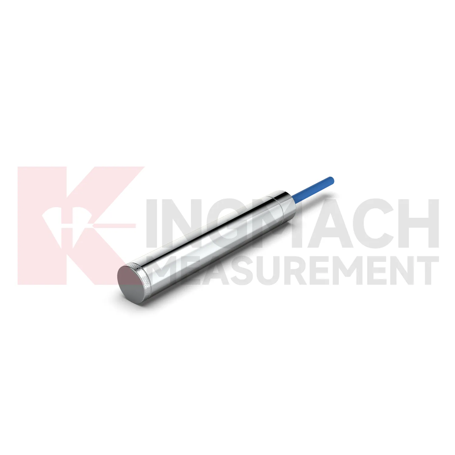
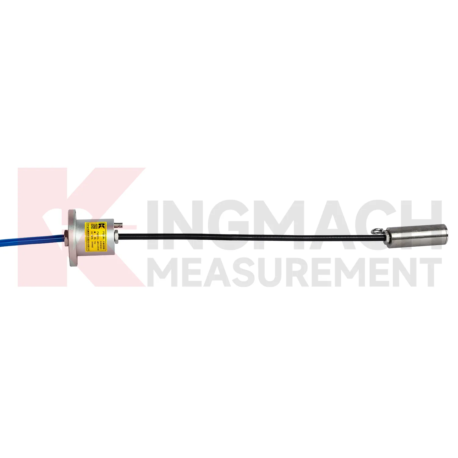
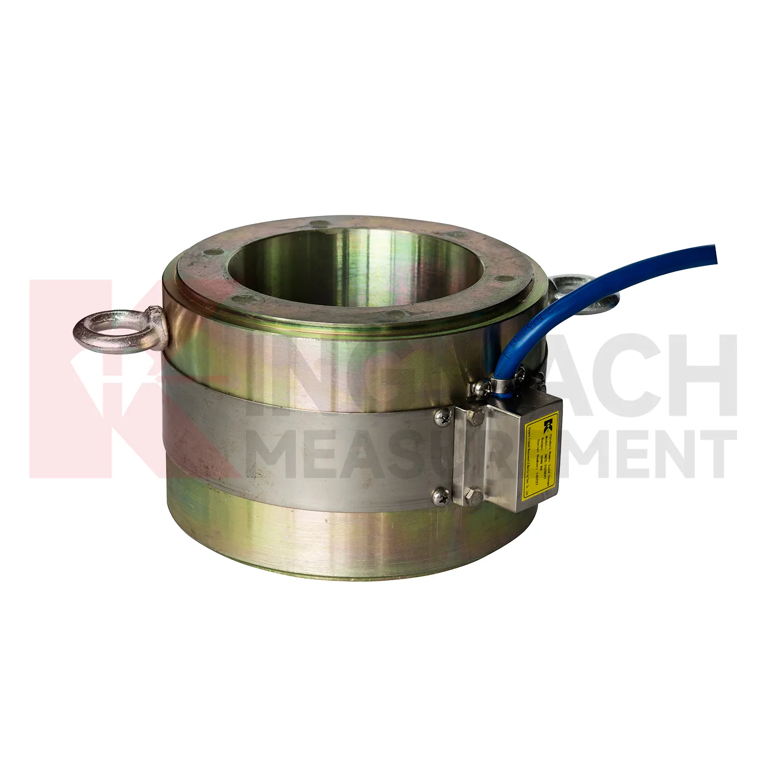
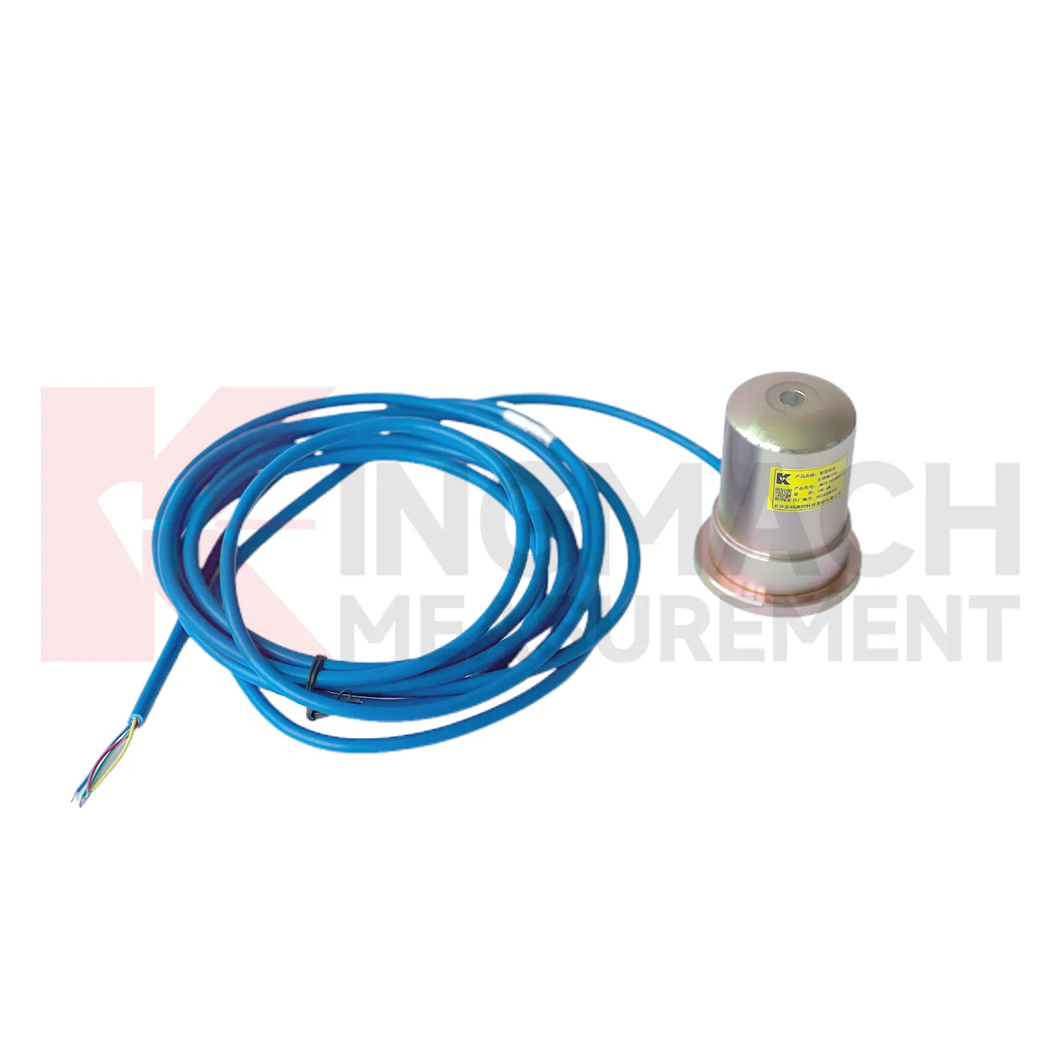
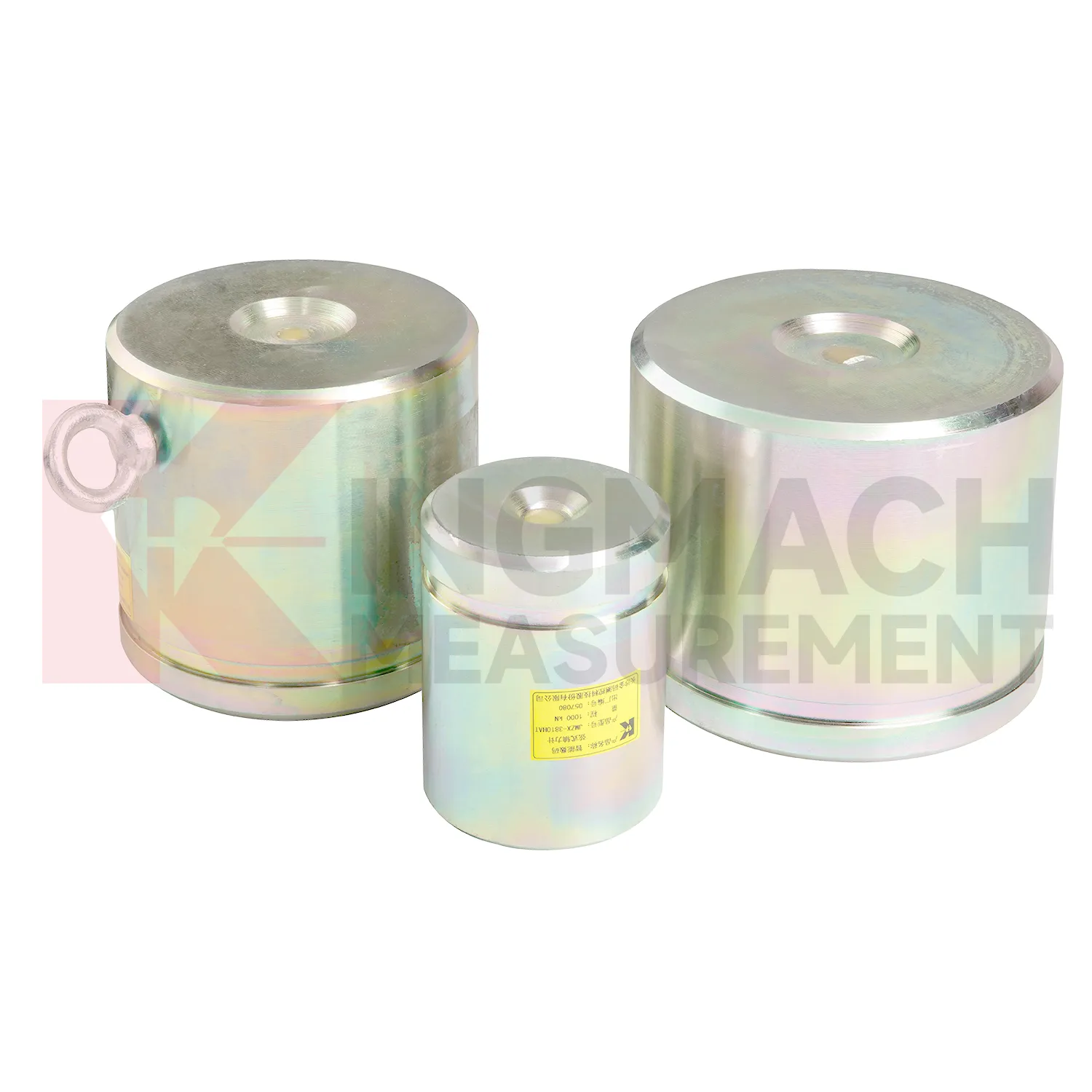
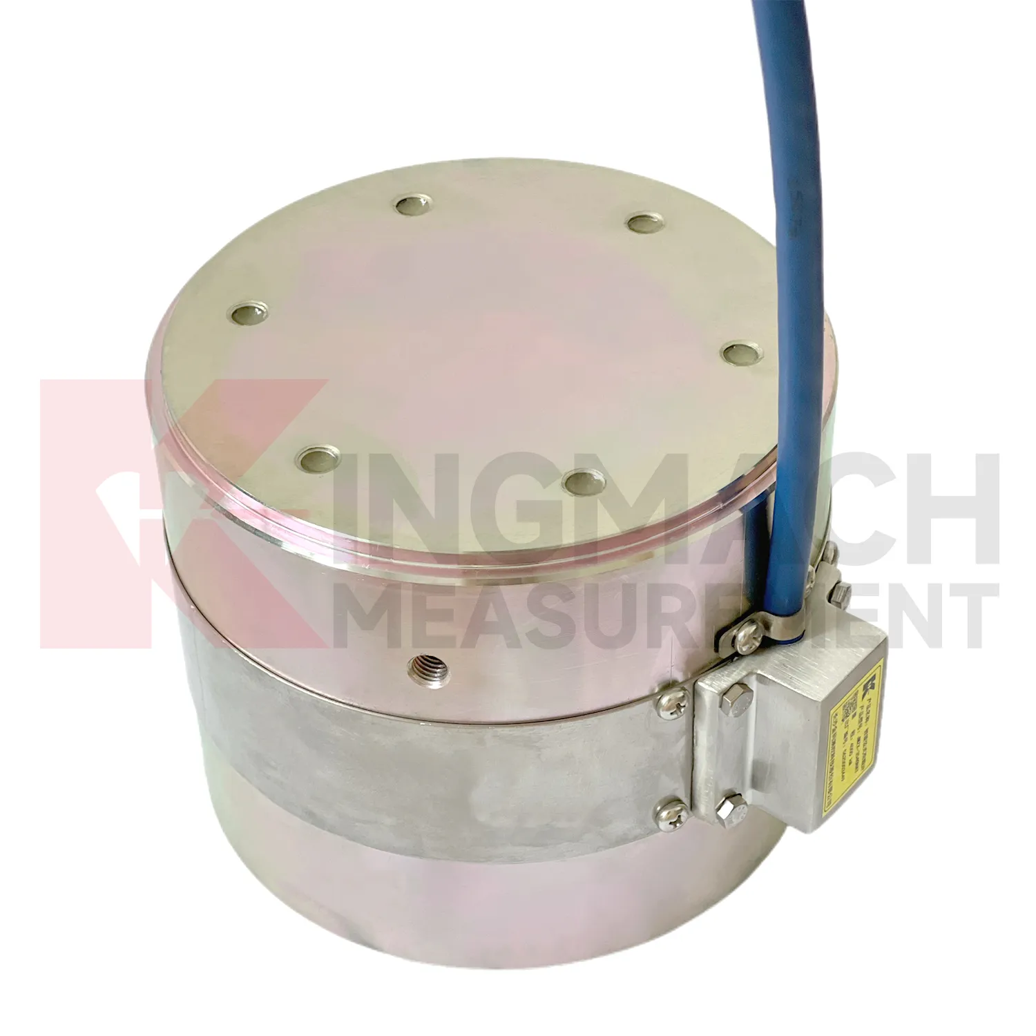
Kingmach load cell wiring diagram descriptions should be read together with the data chain around the sensor. A hollow load cell can cover 500 kN to 8000 kN with a long service design, while the solid load cell line reaches 10000 kN with 0.5%FS precision. The axial force meter adds direct kN display and a 1 MPa waterproof rating for support load monitoring. Smart models include memory for calibration information, zero values, temperature data, and stored measurement records. These are not decorative features. They reduce uncertainty when many sensors are installed across a bridge, tunnel, foundation pit, dam, or rail project. Kingmach supplies readouts and data acquisition equipment, so a single instrument can be used for manual reading during installation and later connected to centralized monitoring if the owner requires it. The better specification path starts with the monitored member, expected load range, access condition, waterproof exposure, temperature swing, cable distance, and reporting method, then selects the model around those constraints. Kingmach's after-sales information also refers to warranty service, anti-static and shockproof packaging, and technical response support. Those points are useful in force monitoring because sensor damage, delivery handling, and setup questions can all affect whether the first readings are trusted.
Application of load cell wiring diagram
In railways, highways, and transport corridors, load cell wiring diagram can monitor bridge support loads, subgrade pressure, retaining structure forces, and temporary works near active traffic. The difficulty is that access windows are short, vibration is frequent, and data gaps can create uncertainty during maintenance review. Kingmach smart load products support digital output, anti-interference transmission, built-in temperature correction, and stored model or calibration information. Solid load cells list 1000 kN to 10000 kN ranges and 0.5%FS precision, while axial force meters cover 200 kN to 3000 kN for support load points. These specifications suit high capacity structural members and staged construction near operating routes. A monitoring plan should record traffic condition, construction activity, temperature, and any maintenance event near the sensor. For owners, the value lies in trend comparison: whether support loads change after traffic opening, whether subgrade pressure rises after heavy rainfall, or whether temporary structures remain within expected force limits before removal. For transport corridors, the inspection schedule should account for possession windows, traffic vibration, and safe access. Remote acquisition may reduce field visits, but periodic visual checks still catch damaged cables, water entry, and loose junction boxes. Access for inspection should also be planned before backfilling, because later hardware checks may be harder than taking the reading itself.
The future of load cell wiring diagram
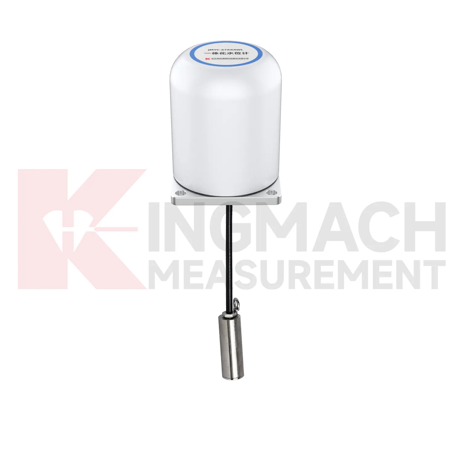
Geotechnical use of load cell wiring diagram will become more connected to environmental monitoring. Earth pressure cells with 0.3 MPa to 8 MPa ranges and 0.001 MPa resolution can already record soil or contact pressure, but future value comes from reading pressure with rainfall, groundwater, seepage, settlement, and slope movement. A pressure increase after rain may be acceptable in one slope and worrying in another, depending on the ground model and drainage condition. Digital twins can handle that comparison if the data is clean enough. Kingmach's wider catalog, including piezometers, water level meters, settlement sensors, tiltmeters, data loggers, and visualization software, supports that direction. Wireless communication will help remote slopes and embankments, while wired systems may remain preferable for buried points with long service expectations. Future standards for monitoring reports will likely ask for more traceable context around each reading, including sensor range, accuracy, calibration date, and installation depth. That connection makes trend review more useful after storms.
Care & Maintenance of load cell wiring diagram
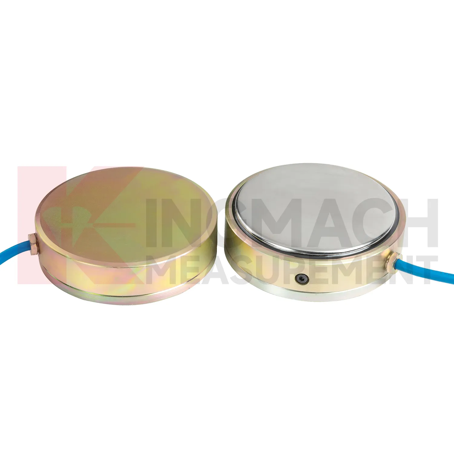
For load cell wiring diagram used in bridge cable or anchor monitoring, maintenance should focus on the load path and the environment around the sensor. Hollow load cells list 500 kN to 8000 kN ranges, temperature correction, waterproof durability, and 800 stored measurement records on smart models. These features support long term observation, but they do not replace site checks. During installation, make sure the washer, bearing plate, anchor head, and sensor axis are properly seated. Record the first stable force after locking and keep the temperature reading with it. During operation, inspect cable protection, connector sealing, corrosion exposure, and any change near the anchor zone. Compare force records after seasonal temperature shifts, heavy traffic periods, maintenance work, or extreme weather. If one point changes while nearby points remain stable, check the bearing surface and wiring before treating the reading as structural behavior. A clean maintenance log helps separate sensor issues from real force redistribution.
Kingmach load cell wiring diagram
load cell wiring diagram often sits between design intent and field behavior. Drawings may state the expected force, but site loading can change when excavation sequence, concrete curing, traffic, reservoir level, grouting, or prestressing work changes. Kingmach supplies sensors and acquisition equipment for bridges, tunnels, dams, subways, slopes, foundations, railways, buildings, and hydropower projects. In these settings, the sensor helps reveal whether a member is carrying its share of the load or taking more than expected. The instrument must fit the force range, the bearing surface, the environmental exposure, and the data workflow. A high capacity sensor with poor installation records is still hard to trust. A moderate range sensor with clear calibration, stable zero, protected cable, and a clean reading plan can produce stronger evidence. For that reason, force monitoring should be planned alongside installation details, not added after the site has already become crowded. This is especially useful when the monitored point becomes hidden after the next work stage.
FAQ
Q: How can load cell wiring diagram be connected to a monitoring platform? A: Use compatible readouts, acquisition modules, data loggers, DTUs, and software platforms according to site access, cable distance, power, and reporting requirements. Q: What makes smart models useful in large networks? A: Stored model data, calibration coefficients, zero values, temperature data, and measurement records reduce confusion across many channels. Q: Should manual readings still be kept? A: Yes, manual checks are useful after installation, maintenance, abnormal alarms, or logger changes. Q: How should alarm limits be set? A: Base them on design stage, sensor range, expected load change, temperature behavior, and nearby monitoring points. Q: What data should be reviewed together with force? A: Settlement, displacement, tilt, water level, pore pressure, rainfall, temperature, construction events, and inspection notes.
Reviews
Robert Taylor
The weir flow meter is well-built and delivers accurate measurements. Great value for water management applications.
David Wilson
We purchased displacement transducers and settlement sensors, and the quality exceeded our expectations. Easy installation and reliable performance.
Latest Inquiries
To protect the privacy of our buyers, only public service email domains like Gmail, Yahoo, and MSN will be displayed. Additionally, only a limited portion of the inquiry content will be shown.
Harper***@gmail.comIndia
Dear Sir, we are planning to procure a complete monitoring system including strain gauges, tiltmeter...
Sophia***@gmail.comUnited Kingdom
Good day, we need environmental monitoring sensors including temperature, humidity, and wind sensors...