 ar
ar bg
bg hr
hr cs
cs da
da nl
nl fi
fi fr
fr de
de el
el hi
hi it
it ko
ko no
no pl
pl pt
pt ro
ro ru
ru es
es sv
sv tl
tl iw
iw id
id lv
lv lt
lt sr
sr sk
sk sl
sl uk
uk vi
vi et
et hu
hu th
th tr
tr fa
fa ms
ms hy
hy ka
ka ur
ur bn
bn mn
mn ta
ta kk
kk uz
uz ku
ku
load cell wire diagram
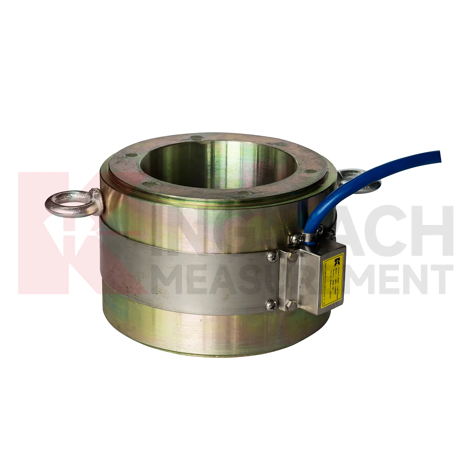
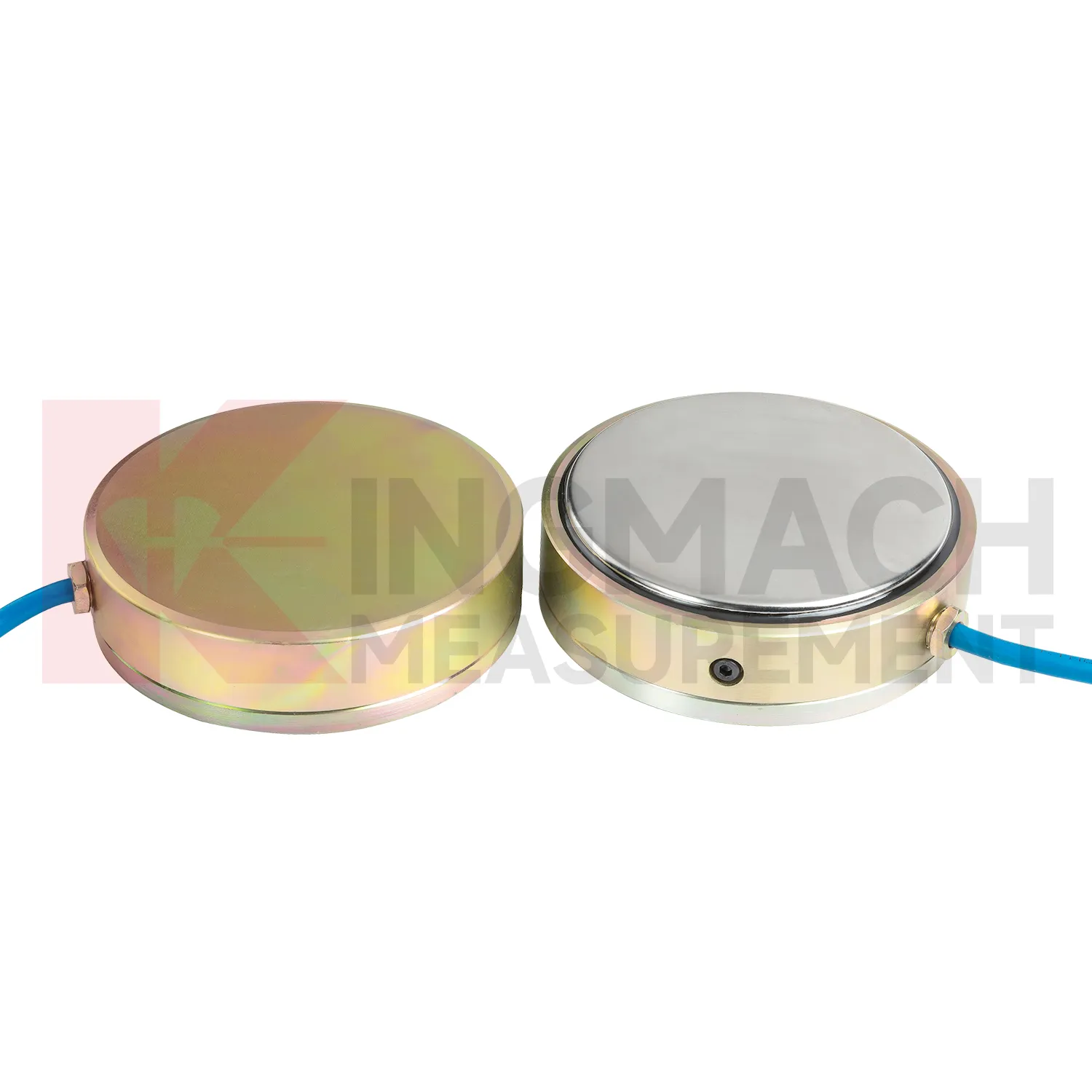
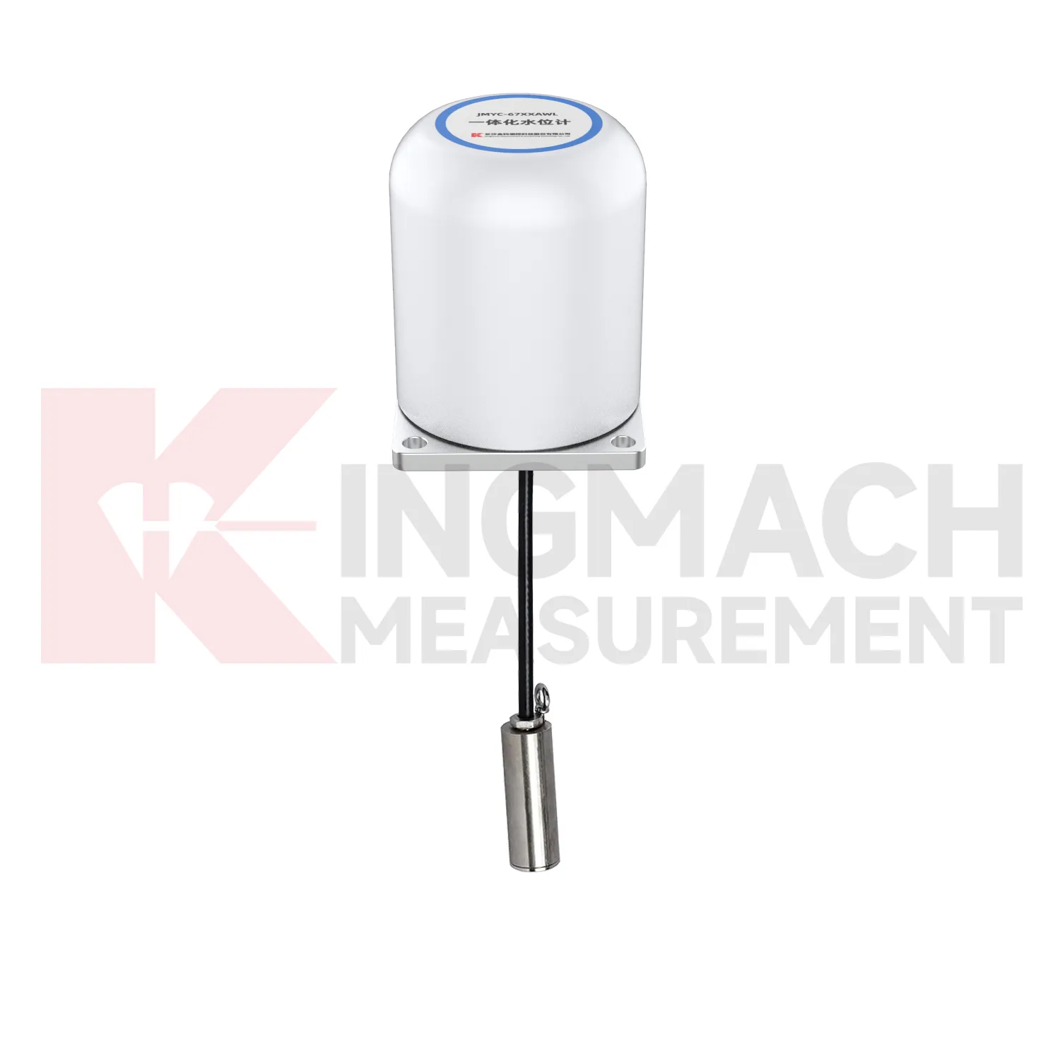
Kingmach load cell wire diagram can also include pressure related sensing where soil or structural contact pressure is the main concern. The JMZX-50XXAT/ATM earth pressure cell family is listed in 0.3 MPa, 0.6 MPa, 1 MPa, 2 MPa, 4 MPa, 6 MPa, and 8 MPa ranges, with 0.001 MPa pressure resolution, 0.5%FS pressure accuracy, and ±0.5°C temperature accuracy. The product information also refers to high strength elastic steel, waterproof and durable construction, a 50 year design life, 800 stored measurement sets, and automated acquisition support. For retaining structures, embankments, dams, tunnels, and foundation pits, those pressure records help engineers understand whether earth load, water influence, compaction, or excavation stage changes are affecting the structure. Kingmach's broader monitoring catalog allows these readings to be compared with settlement, water pressure, displacement, and tilt. That connection is important because pressure change without movement may still indicate a developing load redistribution that deserves closer inspection. The same site places these instruments within a wider monitoring range, including piezometers, water level meters, displacement transducers, settlement sensors, tiltmeters, cables, data loggers, and software. That wider range helps when a project needs force data to be compared with movement, water, and temperature records.
Application of load cell wire diagram
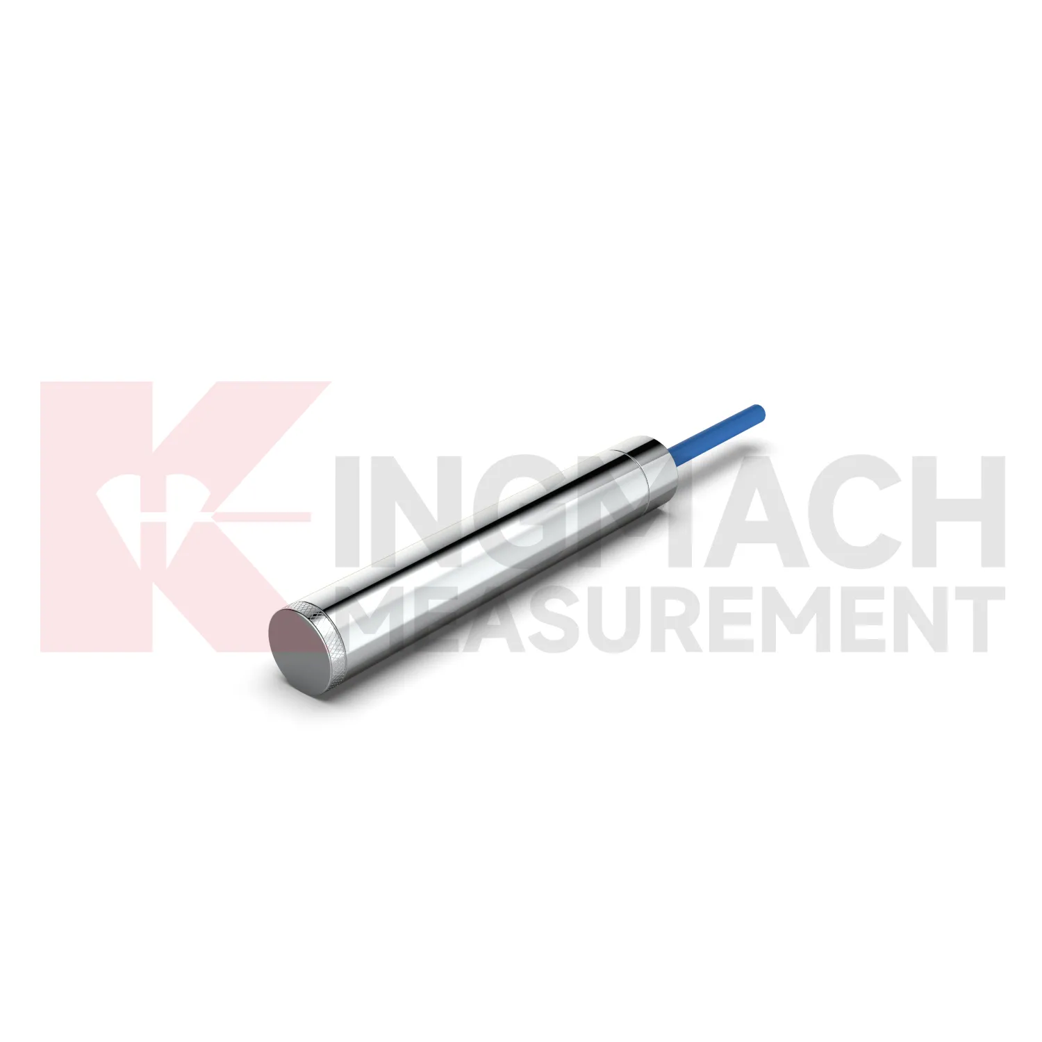
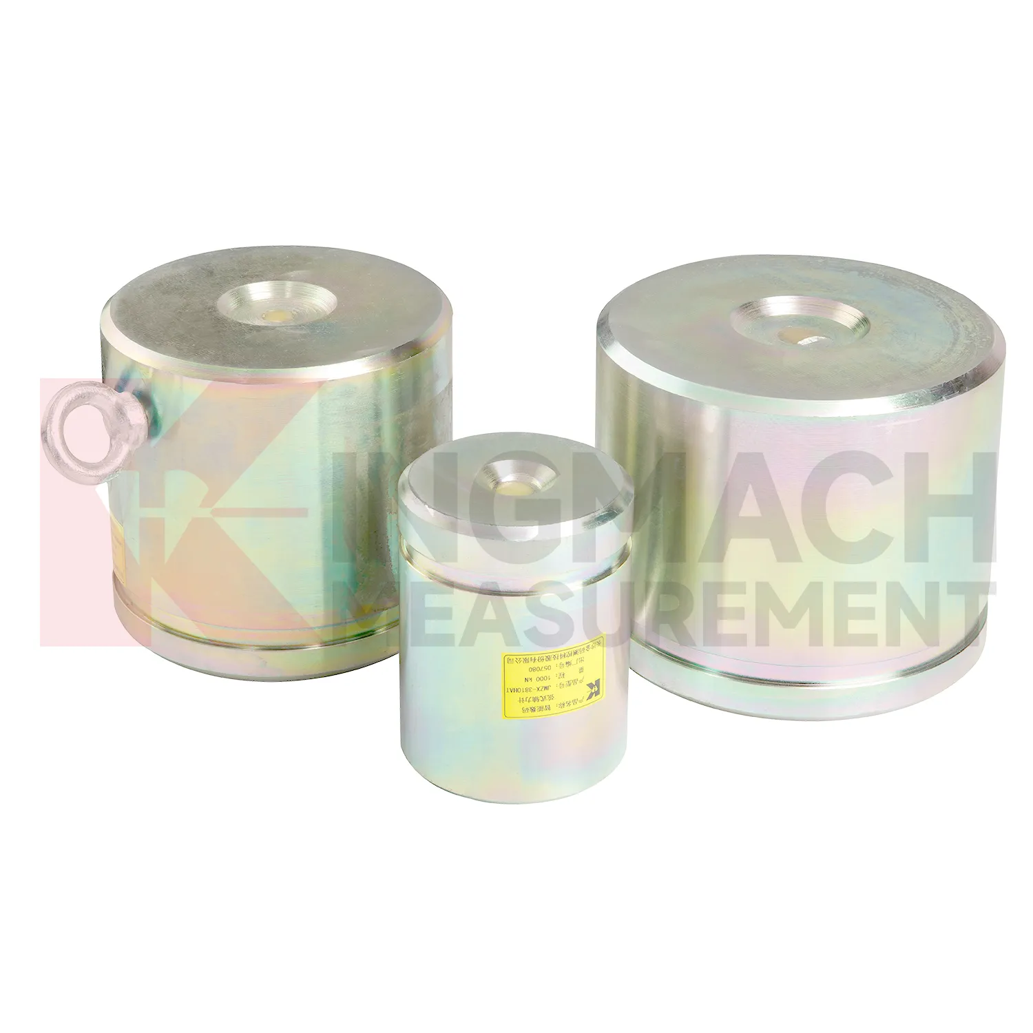
In industrial force testing and heavy equipment monitoring, load cell wire diagram can be applied to presses, jacks, lifting frames, cranes, test benches, fixtures, and custom loading rigs. The pain point is repeatability. A test may pass once, but the owner needs to know whether the next test used the same loading path, sensor range, and calibration basis. Kingmach solid load cells provide high capacity force measurement up to 10000 kN with 0.5%FS precision, while hollow load cells cover 500 kN to 8000 kN and can store 800 measurement records on smart models. Axial force meters provide 200 kN to 3000 kN ranges and direct kN display. These features suit both site acceptance testing and repeated equipment checks. Installation should control centering, bearing plate flatness, side loading, cable strain relief, and zero reading before load is applied. Data becomes stronger when the report records operator, fixture condition, load stage, temperature, and any overload event. For test benches, repeatability also depends on fixture stiffness, alignment, and loading rate. A high accuracy sensor cannot correct a poor mechanical setup, so maintenance should include the test frame and not only the measuring element. The monitoring plan should also define who reviews abnormal data and how quickly a field check must follow a confirmed alarm.
The future of load cell wire diagram
Future load cell wire diagram use will depend on cleaner data pipelines, not only stronger metal parts. Kingmach's smart load cell features, including digital output, long distance transmission, anti-interference performance, temperature correction, and stored parameters, already point toward connected monitoring. In the next few years, more projects are likely to use edge acquisition units that check whether a reading is plausible before it reaches the platform. A sudden force jump can be compared with temperature, cable condition, nearby displacement, and recent construction events. AI based warning tools may help sort routine fluctuation from patterns that deserve inspection, but they will only work when the instrument record is consistent. That places more value on channel naming, calibration certificates, zero checks, installation photos, and maintenance logs. The product direction is therefore practical: robust sensing at the point of load, reliable transmission from difficult sites, and software that helps engineers review trends without losing the original measurement context.
Care & Maintenance of load cell wire diagram
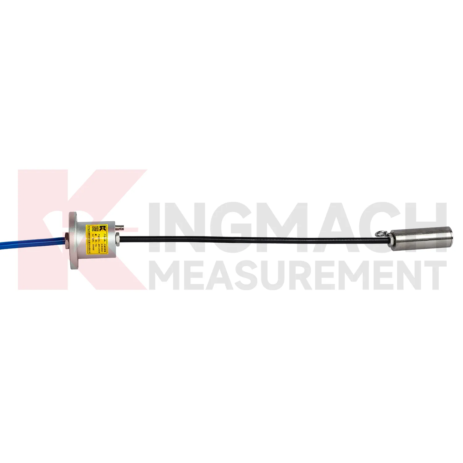
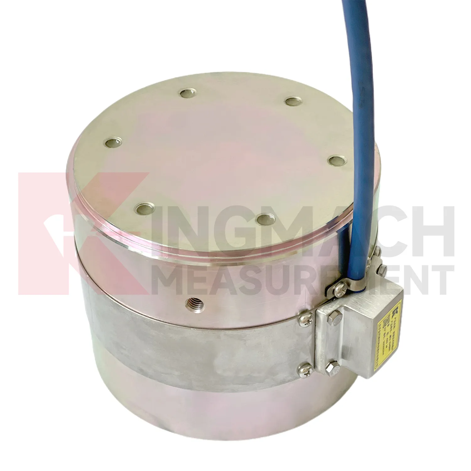
For load cell wire diagram used in bridge cable or anchor monitoring, maintenance should focus on the load path and the environment around the sensor. Hollow load cells list 500 kN to 8000 kN ranges, temperature correction, waterproof durability, and 800 stored measurement records on smart models. These features support long term observation, but they do not replace site checks. During installation, make sure the washer, bearing plate, anchor head, and sensor axis are properly seated. Record the first stable force after locking and keep the temperature reading with it. During operation, inspect cable protection, connector sealing, corrosion exposure, and any change near the anchor zone. Compare force records after seasonal temperature shifts, heavy traffic periods, maintenance work, or extreme weather. If one point changes while nearby points remain stable, check the bearing surface and wiring before treating the reading as structural behavior. A clean maintenance log helps separate sensor issues from real force redistribution.
Kingmach load cell wire diagram
load cell wire diagram gives engineering teams a way to follow load behavior without dismantling the structure. In bridge bearing checks, anchor testing, steel support monitoring, pile tests, and retaining wall pressure work, the measured force can change before cracks, settlement, or visible deformation become obvious. Kingmach product information points to vibrating wire and smart sensing designs, built-in memory, automatic temperature correction, waterproof construction, and direct force display on selected models. These features matter because site readings are often taken by different people across long periods. The instrument needs to preserve its identity and calibration background even when the reading method changes from manual inspection to automated collection. The most useful force record is modest but complete: point name, model, range, coefficient, temperature, cable condition, acquisition channel, and the event that preceded the reading. That is enough to make later engineering review much less speculative. It also helps inspectors decide whether a changed value needs field checking or simple trend review.
FAQ
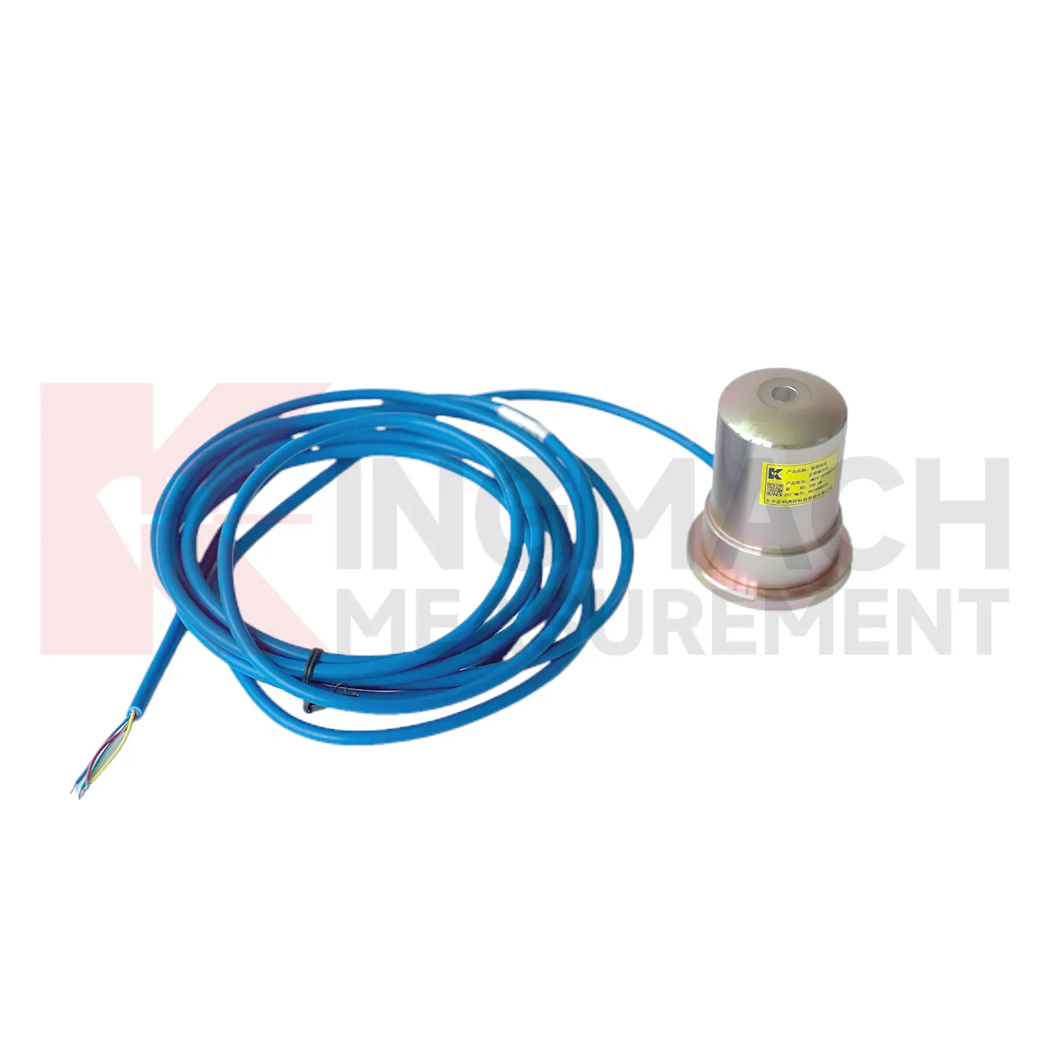
Q: What does load cell wire diagram do in a foundation pit or tunnel? A: It measures axial force in steel supports, anchor load, or pressure change as excavation and support stages progress. Q: Which Kingmach model fits steel support axial force? A: The JMZX-38XXHAT axial force meter is listed from 200 kN to 3000 kN, with 0.1 kN or 1 kN sensitivity and 0.5%FS accuracy. Q: Is it suitable for wet underground sites? A: The axial force meter lists a 1 MPa waterproof rating, but connector sealing and cable routing still need inspection. Q: Why is direct kN display useful? A: It reduces confusion because teams can read axial force directly instead of converting vibrating wire frequency on site. Q: What should trigger extra checks? A: Excavation step changes, rainfall, dewatering, support adjustment, sudden force jumps, or unstable channels.
Reviews
Robert Taylor
The weir flow meter is well-built and delivers accurate measurements. Great value for water management applications.
Michael Anderson
The strain gauges and load cells are extremely accurate and stable. They performed very well in our bridge monitoring project. Highly recommended!
Latest Inquiries
To protect the privacy of our buyers, only public service email domains like Gmail, Yahoo, and MSN will be displayed. Additionally, only a limited portion of the inquiry content will be shown.
Charlotte***@gmail.comUnited Arab Emirates
Hi, we require instrumentation cables suitable for harsh environments. Could you advise on specifica...
Sophia***@gmail.comUnited Kingdom
Good day, we need environmental monitoring sensors including temperature, humidity, and wind sensors...